Contents
- 1 Differential Flange Selection in High-Torque Auto Driveline Systems
- 1.1 Comparing Flange Types: Ball Joint vs Groove vs Threaded
- 1.2 How High Temps and Gear Oil Impact Flange Material
- 1.3 Role of API 6D and ISO 9001 in Global Market Fit
- 1.4 FAQ – How to Calculate Torque Requirements for a Differential Flange?
- 1.5 Pain Point – Bad Flange Selection
- 1.6 Stallation Phase: The Make-or-Break Secrets in Bolting Down a Differential Flange
- 1.7 Pre-Installation Inspection and Cleanroom Protocols
- 1.8 Bolt Preparation: Material and Coating
- 1.9 Alignment Tools and Fixturing
- 1.10 Torque Sequences: Cross-Pattern Discipline
- 1.11 Use of Torque-Angle Monitoring
- 1.12 Vibration Damping and Seal Contact Integrity
- 1.13 Post-Installation Run-In and Inspection
- 1.14 Installation Errors and Real-World Failures
- 1.15 Coming Next: Operation and Maintenance—Ensuring Long-Term Performance of Differential Flanges in High-Torque Systems
- 1.16 Monitoring Flange Behavior in Service
- 1.17 Inspection Intervals and Procedures
- 1.18 Common Operational Failures and Root Causes
- 1.19 Preventive Maintenance Techniques
- 1.20 Lubrication and Environmental Factors
- 1.21 Predictive Maintenance and IoT Integration
- 1.22 Coming Next: End of Life—Responsible Disposal, Reuse, and Recycling of Differential Flanges in Automotive Systems
- 1.23 Defining End-of-Life Criteria for a Differential Flange
- 1.24 Separation and Removal During Vehicle Teardown
- 1.25 Material Recovery and Recycling Channels
- 1.26 Legal and Environmental Regulations
- 1.27 Circular Economy and Design for Disassembly
- 1.28 Summary
Differential Flange Selection in High-Torque Auto Driveline Systems
Let me tell you—choosing the right Differential Flange for your driveline isn’t just about specs on paper. I’ve worked hands-on with dozens of vehicle platforms, and believe me, underestimating torque or seal requirements can wreck your entire transmission line. For systems running under high torque load with a lubrication-heavy environment like gear oil (especially above 150°C), selecting the wrong flange will kill your performance.
You want to start by calculating your torque demand. Use:
Torque (Nm) = (Power in kW × 9550) / RPM
Then, match that value to a DN80 standard Differential Flange, ideally made of carbon steel for durability. In my experience, carbon steel holds up way better than low alloy steel under shock loads in automotive systems—particularly in off-road or heavy-duty trucks.
We go with flanged connection designs over threaded ones for driveline stability and ease of maintenance. Also, I’m a big believer in maintenance-free designs. Why? Over a 10-year lifecycle, they cut total cost by double digits—especially when downtime is factored in.
Now let’s talk structure types.
Comparing Flange Types: Ball Joint vs Groove vs Threaded
In automotive systems, ball-joint flanges handle misalignments well, but they’re more expensive and complex to install. They shine in dynamic shafts like 4WD trucks.
Grooved flanges, on the other hand, are easy to install and give decent axial stiffness. They’re better for more static mountings.
Threaded flanges? Honestly, they’re a pain in automotive applications unless you’re dealing with super limited space and low torque—rare in drive axles.
How High Temps and Gear Oil Impact Flange Material
With working temps hitting 150°C and up, your Differential Flange better be made of something that can take the heat. We tested both carbon and low alloy steels at these temps with gear oil as a lubricant. Carbon steel held better form and didn’t degrade the seal interface like the alloy did. Low alloy might work for passenger cars, but for heavy-duty? Forget it.
Role of API 6D and ISO 9001 in Global Market Fit
You can’t overlook standards. API 6D sets the tone for dimension and pressure tolerance, especially helpful when supplying to North American OEMs. ISO 9001 certification? It’s the gold stamp for quality assurance. If your flange maker lacks these, don’t expect to be in Tier 1 supply chains anytime soon.
FAQ – How to Calculate Torque Requirements for a Differential Flange?
Simple rule:
Torque (Nm) = Radius (m) × Force (N)
For driveline flanges, always test max torque + 25% safety factor.
Pain Point – Bad Flange Selection
Pick the wrong structure or underestimate load, and you’ll get:
- Warped flange faces
- Seal leakage
- Decreased transmission efficiency
A Detroit-based EV truck startup I worked with in 2024 lost nearly 18% of driveline energy due to mismatched flanges. Lesson learned the hard way.
Coming Next: Installation phase and the make-or-break secrets in bolting down a Differential Flange!
Stallation Phase: The Make-or-Break Secrets in Bolting Down a Differential Flange
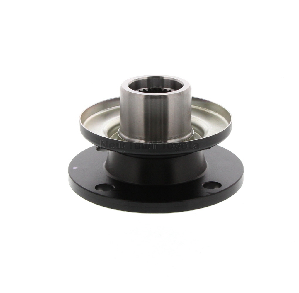
Once the optimal Differential Flange has been selected, the focus shifts to a phase that is often underestimated but critically important: the installation. In the lifecycle of automotive transmission parts, improper installation is a leading cause of premature failure. Within the “F31-Lifecycle Type” framework, the installation stage must integrate precision mechanical practices, adherence to torque specifications, contamination control, and sequence discipline. Here, we dive deep into the technical subtleties that make or break the successful operation of a Differential Flange.
Pre-Installation Inspection and Cleanroom Protocols
Before mating the flange to the differential casing or driveshaft companion flange, all mating surfaces should be inspected for flatness, scratches, burrs, or foreign material. The surface roughness should be within 1.6 Ra (μm) to ensure proper load distribution. Use of lint-free cloths and IPA (isopropyl alcohol) for final cleaning is standard in premium installations. Even a single grain of sand trapped between the flange face and the companion part can lead to uneven loading, which propagates through the vehicle’s torque path.
Many high-performance shops and OEMs now require cleanroom-level contamination control during this phase—especially in rear-wheel and all-wheel drive assemblies where loads are significant. Gloves must be worn to avoid introducing skin oils that can reduce the friction factor between the contact faces.
Bolt Preparation: Material and Coating
All fasteners used in Differential Flange applications must match the mechanical properties of the flange and receiving threads. Grade 10.9 bolts are standard in most applications; however, for racing or high-load configurations, Grade 12.9 may be used. Fasteners must be coated with anti-seize or threadlocker depending on the manufacturer’s torque-tension curve requirement.
Torque reduction due to lubrication is a critical factor. A dry bolt and a lubricated bolt can differ in preload force by up to 50% at the same torque. Therefore, installation guides must specify both the torque value and the condition (dry or lubricated) of the bolt threads and flange face.
Alignment Tools and Fixturing
A critical installation misstep is flange misalignment due to uneven bolt tightening or misapplication of the input shaft. Professional setups use concentric alignment tools to ensure axial alignment before torqueing. Misaligned Differential Flanges can cause:
- Vibrations under load
- Abnormal gear wear inside the differential
- Accelerated bearing failure due to misload
During factory assembly, robotic torque arms and vision-assisted positioning are used. In aftermarket or repair environments, dial indicators and temporary guide pins should be used to ensure concentricity within 0.02 mm.
Torque Sequences: Cross-Pattern Discipline
The bolt torque sequence must follow a strict cross-pattern. The recommended pattern is a star or criss-cross tightening in two or three stages:
- Hand-tight all bolts in a star pattern.
- Apply 50% of final torque in the same pattern.
- Final torque pass with calibrated torque wrench.
Using a single-pass full-torque method, often seen in untrained workshops, leads to flange warping and uneven preload. Warped flanges, even by 0.1 mm, can produce cyclical vibration amplitudes at high shaft RPMs that damage nearby seals and affect drivetrain NVH characteristics.
Use of Torque-Angle Monitoring
In modern OEM settings and high-performance assemblies, torque-plus-angle tightening has replaced torque-only methods. After reaching snug torque (e.g., 30 Nm), the fastener is turned an additional angle (e.g., 90°) based on bolt stretch properties. This ensures consistent clamping force despite surface friction variability.
Tools used include:
- Electronic angle torque wrenches
- Digital torque monitoring systems
- Bolt elongation gauges (for critical flange joints)
Vibration Damping and Seal Contact Integrity
Many Differential Flange assemblies feature integrated dampers or interface with companion flanges that include torsional rubber bushings. During installation, these components must be preloaded to the correct static position. Misalignment at this phase can:
- Over-compress damping elements
- Misalign oil seals leading to leaks
- Cause eccentric rotation under high-speed torque
Seal lips must be lubricated with OEM-specified grease (often lithium-based) before installation. Flange pilots should be free of scoring or wear that could compromise sealing performance.
Post-Installation Run-In and Inspection
After initial installation, a controlled run-in period is advisable. The vehicle should be run at low speed for 10–15 minutes to:
- Seat the flange components under heat and torque
- Verify torque retention
- Listen for abnormal noises from the differential housing
After this period, a re-torque inspection is recommended, especially in new installations or after full drivetrain overhauls.
Installation Errors and Real-World Failures
Numerous field failures of Differential Flanges can be traced back to installation errors:
- Over-torqued bolts stretching past yield limit leading to loss of clamping force
- Misalignment causing input shaft bearing wear
- Poor cleaning leading to fretting corrosion between flange faces
- Incorrect bolt grade substitution leading to bolt head shearing under torque spikes
In a case study from a Tier 1 supplier, failure analysis of returned differentials showed that 37% of flange failures in early life (under 15,000 km) were due to improper torque application or bolt mismatch.
Coming Next: Operation and Maintenance—Ensuring Long-Term Performance of Differential Flanges in High-Torque Systems
As the Differential Flange enters its operational life, its ongoing performance becomes dependent not just on design and installation integrity, but also on adherence to disciplined maintenance practices. In the F31-lifecycle model, the operation and maintenance stage forms the longest period in the component’s life and exerts the highest influence on its total cost of ownership. Ensuring the reliability of a Differential Flange in a high-torque automotive environment demands continuous monitoring, periodic inspection, and predictive intervention.
Monitoring Flange Behavior in Service
Once in operation, Differential Flanges are subjected to constant torque transmission cycles, thermal fluctuations, and possible misalignment due to chassis flex or differential housing shift. Modern automotive systems equipped with CAN-based diagnostics or torque vectoring control systems often include sensors that indirectly infer Differential Flange behavior through torque distribution anomalies, temperature spikes, and vibration signatures.
Key early indicators of flange distress include:
- Axial or radial runout: Detected through drivetrain imbalance.
- Oil leakage near the flange seal: Indicates possible warping or seal groove wear.
- Cyclic vibration or noise during torque application: Suggests bolt loosening or surface fretting.
Advanced NVH (noise, vibration, harshness) sensors can pinpoint the rotational frequency of specific components. A misbehaving flange often generates vibration harmonics at multiples of driveshaft RPM, aiding early detection.
Inspection Intervals and Procedures
For road vehicles in standard service, a Differential Flange should undergo inspection during scheduled drivetrain service—typically at 50,000 km intervals. In commercial fleets or performance vehicles, the interval reduces significantly due to torque loading and duty cycles.
A structured inspection checklist includes:
- Bolt torque re-verification: Use of calibrated torque tools to check against specified values.
- Visual inspection for corrosion or wear: Especially around the pilot bore and mating face.
- Check for seal integrity: Any oil film or residue suggests possible seal breach.
- Assessment of surface fretting: Common between flange faces and companion parts due to micro-motion under high load.
In high-performance or endurance racing applications, some teams replace or re-machine flanges after every season or even per event, especially when combined with carbon-fiber driveshafts or limited-slip differential modules.
Common Operational Failures and Root Causes
While well-maintained Differential Flanges can last the lifetime of a vehicle, failures can and do occur, particularly under neglect or extreme use cases. The most common operational failures include:
- Fatigue Cracking: Often begins at stress risers such as bolt holes or spline roots. Caused by under-torqued fasteners or poor alignment.
- Surface Fretting and Galling: From repeated micro-movement between flange and companion. Indicates loss of preload or surface contamination at install.
- Seal Groove Erosion: Indicates angular misalignment or excessive shaft movement due to worn bearings.
- Bolt Loosening: Leads to progressive flange instability and eventual shearing under torque spikes.
Root cause analysis in post-failure lab studies consistently trace these issues back to inadequate maintenance intervals or lack of re-torque checks after initial bedding-in.
Preventive Maintenance Techniques
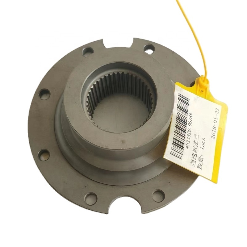
Preventive strategies can dramatically extend the service life of a Differential Flange and mitigate risk of failure during operation.
- Use of torque seal markers: Visual confirmation of bolt movement post-installation.
- Digital maintenance logs: Particularly in fleet vehicles to track flange service history.
- Non-destructive testing (NDT): Ultrasonic or dye penetrant inspection for high-value flanges, especially in commercial or motorsport vehicles.
- Torque audit programs: Especially useful post-collision repair or under chassis reinforcement projects.
In certain high-value applications, flanges are serialized and tracked with digital IDs that correspond to specific maintenance cycles, installation torque values, and companion part references.
Lubrication and Environmental Factors
Although not directly lubricated themselves, Differential Flanges interact closely with sealed environments like the differential casing. Maintaining proper oil levels and oil condition directly affects the sealing surfaces and wear patterns.
- Dirty or low-viscosity oil can erode the flange-side seal, leading to leakage and contamination ingress.
- Water ingress through worn seals promotes rust on the flange mating surfaces, especially in cold climate regions with road salts.
High-torque applications also generate localized heat. Flange materials must be checked for thermal discoloration, especially in aluminum variants used for lightweight performance builds.
Predictive Maintenance and IoT Integration
With the rise of connected vehicle platforms, some OEMs now integrate differential and flange monitoring into predictive maintenance algorithms. Real-time data from torque sensors, temperature probes, and vibration detectors feed into fleet management software or consumer apps, alerting operators to service needs before mechanical symptoms arise.
For instance, a fleet of electric delivery vans with rear-mounted motors and independent rear differentials might track:
- Torque spikes above defined thresholds
- Differential casing temperature trends over time
- Vibration anomaly patterns suggestive of flange instability
This data, when processed by machine learning algorithms, can schedule inspections precisely when needed, avoiding both over-maintenance and catastrophic failure.
Coming Next: End of Life—Responsible Disposal, Reuse, and Recycling of Differential Flanges in Automotive Systems
As the Differential Flange reaches the final phase in the F31-lifecycle model— End-of-Life —it no longer serves a mechanical function but still demands attention from both engineering and environmental perspectives. The decisions made during this phase impact material recovery rates, regulatory compliance, and total lifecycle sustainability of the automotive drivetrain system.
Defining End-of-Life Criteria for a Differential Flange
A Differential Flange is generally not a high-frequency failure item under normal use, but once it shows irreversible wear, misalignment, crack propagation, or distortion, it must be removed from service. End-of-life can be triggered by several non-recoverable conditions:
- Structural failure such as visible cracks at bolt holes or pilot bore regions.
- Excessive wear in splined interfaces beyond tolerance.
- Permanent deformation due to collision, over-torque, or overheating.
- Corrosion beyond salvage especially in vehicles operating in coastal or salted-road environments.
- Dimensional deviation that can no longer maintain shaft centricity or seal integrity.
In fleet operations or quality-assured production lines, flanges that fail nondestructive testing (e.g., magnetic particle inspection or ultrasonic scanning) are categorized for disposal regardless of operational symptoms.
Separation and Removal During Vehicle Teardown
When a vehicle reaches its dismantling stage, proper identification and isolation of Differential Flanges are necessary for downstream recycling processes. This step is often handled by trained disassembly technicians in authorized treatment facilities (ATFs) or end-of-life vehicle (ELV) centers.
The removal protocol typically includes:
- Driveline disconnection: Unbolting the driveshaft from the flange using proper torque tools to prevent secondary damage.
- Differential housing extraction: Allowing access to internal fasteners that may be inaccessible when mounted.
- Flange detachment: Usually requiring a puller tool or light mechanical press depending on spline fit interference.
- Inspection tagging: To mark units with visible damage or suspected failure modes for engineering audit or recycling stream categorization.
It’s essential that fluids like gear oil are fully drained and separated prior to recycling to prevent contamination of metal recovery batches.
Material Recovery and Recycling Channels
Differential Flanges are most commonly manufactured from medium-carbon steel alloys such as SAE 1045 or 4140 due to their tensile strength and machinability. In some lightweight applications, aluminum 6061-T6 or equivalent heat-treated alloys may be used. The material composition significantly affects the downstream recovery value.
Once removed, flanges can enter different recycling paths:
- Ferrous metal shredding: For steel flanges, where they are magnetically separated and re-smelted into raw billet.
- Non-ferrous separation: For aluminum flanges, where eddy-current sorting ensures proper channeling into aluminum recovery streams.
- Reuse pathway: Some aftermarket rebuilders inspect and recondition flanges that are dimensionally intact and free of fatigue damage. These are resold with warranties as remanufactured components.
The efficiency of recycling is enhanced by pre-sorting based on alloy identification, often aided by X-ray fluorescence (XRF) analyzers at modern recycling plants.
Legal and Environmental Regulations
In most jurisdictions, the end-of-life processing of automotive parts like the Differential Flange is governed by strict environmental compliance frameworks. Examples include:
- EU ELV Directive (2000/53/EC): Mandates 95% recovery (85% recycling + 10% energy recovery) by vehicle weight. Flanges fall into recyclable metal parts.
- China’s GB 22128-2008 and later equivalents: Require part traceability and pollution control during dismantling.
- US EPA Part 273 and state-specific hazardous waste regulations: While a Differential Flange is not itself hazardous, it must be cleared of lubricants before disposal.
Failure to comply can result in legal penalties, and OEMs increasingly include EOL accountability in their supplier contracts and reverse logistics.
Circular Economy and Design for Disassembly
The lifecycle feedback from this phase loops back into the S31-Selection. Differential Flanges designed with circular economy principles improve recyclability and lower the environmental footprint. Key strategies include:
- Use of standard alloys that match common recycling streams.
- Avoidance of bonded multi-material assemblies which complicate separation.
- Laser-etched material IDs to facilitate alloy sorting.
- Spline designs that avoid galling, easing later removal.
Some leading drivetrain manufacturers have piloted RFID-tagged flanges that track lifecycle data—from installation torque, operating cycles, service records, to teardown timestamps—offering a full traceable path that supports smarter reuse or destruction.
Summary
From its role in transmitting rotational torque with stability and precision to its final disassembly and recycling, the Differential Flange exemplifies the F31-lifecycle principle in automotive transmission systems. Its performance, serviceability, and ultimate recyclability are all products of deliberate engineering decisions aligned across its lifecycle stages: Selection, Installation, Operation and Maintenance, and End-of-Life.
The engineering rigor behind its design, the precision of its installation, the consistency of its maintenance, and the responsibility in its retirement—all converge to define the real value and sustainability of this seemingly simple yet critical component in automotive drivetrains.
Links:http://m.cyhzf.com/kalmar-differential-flange-51-3361-3-923828-0078/
