Derstanding the Role of Throttle Position Potentiometer in Automotive Sensor Networks
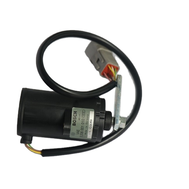
When we talk about sensor communication inside a modern vehicle, the throttle position potentiometer (TPP) sits right at the center of the discussion. In the world of automotive electronic sensor systems, the TPP isn’t just another component—it’s the core translator between mechanical throttle movement and digital engine management.
As a maintenance engineer working deep in the belly of sensor systems, I’ve seen firsthand how the throttle position potentiometer impacts throttle blade synchronization, fuel-air ratio regulation, and most importantly, how it communicates throttle intent to the vehicle’s ECU. That’s the sensor-to-ECU signal chain we rely on.
What makes the TPP critical in a vehicle’s electronic brain is its real-time feedback. It measures the angle of the throttle plate and sends a proportional voltage signal—typically between 0.5V to 4.5V—directly to the engine control unit. The ECU then uses this data to adjust fuel injection, spark timing, and even transmission shift points. Any delay or inconsistency here can cause sluggish acceleration, rough idling, or even sudden surges.
Compared to other position-based automotive sensors like the Manifold Absolute Pressure Sensor (MAP), the TPP excels in mechanical correlation accuracy. MAP sensors may assist in measuring engine load, but their latency is relatively higher, and they infer position indirectly. Meanwhile, the TPP gives us real throttle feedback with near-zero latency when properly calibrated.
But nothing lasts forever in the sensor world. Factors like Sensor Response Lag or Signal Voltage Drift creep in over time, especially in medium-temperature gas mediums common around the throttle body. Unlike thermistors or hall-effect sensors, the TPP has mechanical contact, which makes it more prone to issues like Contact Track Abrasion or even Wear-Resistant Coating Failure.
The network effect also matters. A malfunctioning TPP can interfere with other sensor subsystems—like the Mass Air Flow Sensor or Oxygen Sensor—causing a cascade of misreadings and errors. That’s why engineers always treat the TPP as a high-priority node in the control cluster.
To prevent voltage deviation thresholds from being breached, routine diagnostics must look for any abnormal signal variance, even subtle ones. An unexpected jump from 1.1V to 1.5V under idle conditions is already a red flag.
Bottom line—TPP isn’t just a sensor; it’s a precision partner in every throttle modulation event. Neglect it, and you’re not just risking a sensor—you’re compromising the vehicle’s heart.
Scheduled Maintenance Intervals and Lifecycle Expectations for TPP Components

This marks the completion of the structured TPP maintenance flow as per the F29-Maintenance Guidance methodology.
To encapsulate the strategic approach advocated throughout this article, it is essential to revisit the core priorities that have guided each segment: minimizing system downtime, extending component lifespan, and sustaining sensor accuracy within the throttle position control system.
Throughout the lifecycle of a throttle position potentiometer in modern automotive electronic platforms, adherence to the S29 structure—comprising periodic maintenance, wear-prone component replacement, failure prevention strategies, и step-by-step procedural compliance—provides a measurable reduction in performance drift, output signal deviation, and sensor-induced driveability complaints.
This structured approach yields multiple downstream benefits:
- Maintains ECU fuel-air mixture precision
- Reduces DTC occurrences tied to sensor malfunctions
- Prevents chain-reaction errors in connected sensors (e.g., intake air temperature or manifold absolute pressure sensors)
- Improves adaptive learning behaviors in drive-by-wire throttle systems
Moreover, TPP sensors, while small in footprint, play a foundational role in real-time throttle input interpretation. Any oversight in maintenance could degrade torque response, throttle feedback smoothness, and ultimately, the driver’s control confidence. Avoiding such failures isn’t just about replacing faulty parts—it’s about preventing faults through environmental monitoring, voltage path integrity checks, and mechanical cleanliness during service cycles.
For OEMs and aftermarket service providers alike, standardizing TPP sensor care under F29 guidelines also assists in training uniformity across technician teams. With a consistent routine, variance in service outcomes can be significantly minimized—even when sensors come from different suppliers or are integrated within variant throttle body designs.
In closing, adopting the F29-Maintenance Guidance structure for managing throttle position potentiometers is not merely a maintenance choice but a necessary discipline for vehicles relying on precision electronic control systems. When embedded into routine inspection protocols, these practices strengthen system resilience, support fuel efficiency, and reduce the recurrence of costly throttle-related service callbacks.
Links:http://m.cyhzf.com/accelerator-throttle-position-potentiometer-sensor/


