When it comes to upgrading the heart of heavy-duty mechanical systems, one component silently drives performance, reliability, and lifecycle success: Slide Plate. In my years of field work and system design, I’ve seen poorly chosen sliding interfaces lead to disastrous downtime, ballooning maintenance costs, and even safety failures. But with smart Slide Plate integration—especially under high-temp, solid-particle loads—you can flip the script.
Contents
- 1 Slide Plate Role Inside Mechanical Sliding Component Systems
- 2 Structural Synergy – Slide Plate vs Wear Pad, Guide Strip, and Others
- 3 Load Transfer Logic and Friction Pairing
- 3.1 S37-Engineering Variables Defining Slide Plate Performance
- 3.2 1: Contact Surface Material Composition
- 3.3 2: Thermal Expansion Tolerance
- 3.4 3: Coefficient of Friction Under Operational Conditions
- 3.5 System Deployment Scenarios
- 3.6 Economic Considerations by Variable
- 3.7 S37-Failure Modes and Engineering Countermeasures in Slide Plate Systems
- 3.8 1: Surface Delamination
- 3.9 2: Cold Flow and Plastic Creep
- 3.10 3: Fretting Corrosion at Anchor Interfaces
- 3.11 4: Thermal-Induced Plate Locking
- 3.12 5: Accelerated Wear Track Formation
- 3.13 Predictive Maintenance and Design Integration
- 3.14 Failure Response Economics
- 3.15 S37-Lifecycle Extension Through Hybridized Slide Plate Systems
- 3.16 Tri-Layer Hybrid Slide Plates
- 3.17 Retrofitting Hybrid Plates into Existing Mechanical Systems
- 3.18 Total Lifecycle Cost Modeling for Hybrid Slide Plate Adoption
Slide Plate Role Inside Mechanical Sliding Component Systems
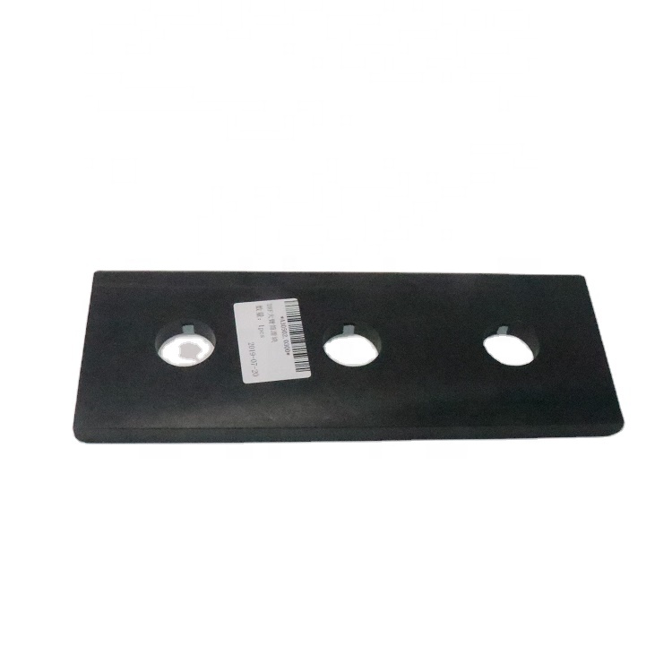
Slide Plate isn’t just a passive wear item. It’s the central player in dynamic load transfer and friction management—crucial in heavy-duty systems like hydraulic presses, ore conveyor rails, and bearing supports in bridge mechanics. In high-load scenarios, Slide Plates take the stress of linear movement, absorbing mechanical drift and maintaining structural alignment under heat, vibration, and particle abrasion.
In integrated architecture, Slide Plate sits within a synergy of elements like Wear Pads, Guide Strips, and Shoe Plates. Each plays a role, but the Slide Plate’s job is unique: it creates a controlled, lubricated (or dry-lubricated) interface between fixed and moving bodies. This allows structural systems to move without introducing misalignment or overheating.
A mistake I often see? Engineers lump Slide Plates together with Slide Bearings or Guide Shoes. Wrong move. Slide Bearings rotate; Slide Plates glide. Mislabeling costs more than just nomenclature—it causes system failures.
Structural Synergy – Slide Plate vs Wear Pad, Guide Strip, and Others
Let’s break down the structural integration and differences.
- Wear Pad is passive—it only resists friction. Slide Plates dynamically support and guide heavy axial loads.
- Guide Strip handles lateral guidance but lacks load-bearing verticality and material diversity.
- Shoe Plate offers foundational support but isn’t optimized for repeat motion in abrasive environments.
- Slide Bearing facilitates rotational load—Slide Plates? Linear displacement only.
In modern ASME-guided designs (Section VIII, Division 1), Slide Plate selection dictates how load paths move along steel subframes, guided runners, or baseplate weldments. The wrong choice means uneven thermal expansion, bolt shear, or weld fatigue—especially in DCS-integrated systems where displacement has to be monitored precisely.
Load Transfer Logic and Friction Pairing
Slide Plates aren’t a plug-and-play item. Their effectiveness depends on your sliding path geometry, load transfer flow, and friction pairing.
- Use PTFE-over-steel Slide Plates for low-friction, medium-load operations.
- Use hardfaced carbon steel in dusty, high-abrasion mining applications.
- Don’t ignore load axis alignment. A Slide Plate misaligned by 2 degrees under 40 tons load can cause premature weld cracking.
Combine Slide Plates with wear plates designed for coefficient of friction as low as 0.06 (PTFE) or as high as 0.4 (bare carbon steel) to fine-tune system behavior. For system designers, this means pre-modeling friction torque impacts using finite element stress simulations—something many overlook.
Coming up next: Deep dive into the five engineering variables that define your Slide Plate performance under real-world stress.
S37-Engineering Variables Defining Slide Plate Performance
In the world of mechanical sliding components, Slide Plates operate under a constant barrage of stressors: load variations, thermal expansion, abrasive environments, and continuous movement. To understand their real-world performance, we must dissect the five engineering variables that directly influence their behavior and reliability. These are:
- Contact Surface Material Composition
- Thermal Expansion Tolerance
- Coefficient of Friction under Operational Conditions
- Compressive Load Capacity
- Wear Resistance Curve over Time
Let’s examine each of these variables through the lens of system architecture, technical formulation, deployment considerations, and economic impact.
1: Contact Surface Material Composition
The surface material of a Slide Plate is the primary interface through which loads are transferred. The most prevalent materials include PTFE, bronze, graphite-based laminates, and hardened steel composites. Each material provides a unique blend of friction coefficient and resilience.
- PTFE (Polytetrafluoroethylene): Offers an exceptionally low friction coefficient (0.05–0.1), but its deformation threshold is limited under high compressive forces (>2000 psi).
- Bronze-Graphite Composites: Slightly higher friction (0.1–0.18) but demonstrate excellent thermal resistance and moderate self-lubrication.
- Hardened Steel Alloys: Less prone to deformation under high pressure (up to 10,000 psi), though they demand external lubrication.
For optimized performance, system-level architecture must account for material pairings: a PTFE upper plate against a stainless steel lower plate prevents galling and maintains efficiency under lateral movement.
Material composition affects:
- Frictional energy losses
- Heat generation rate
- Long-term surface degradation
2: Thermal Expansion Tolerance
Slide Plates often operate in environments subject to large temperature fluctuations—from sub-zero outdoor installations to high-heat manufacturing zones. Thermal expansion mismatches between materials can induce warping or buckling.
The thermal coefficient of expansion (TCE) for materials is crucial:
- PTFE: ~120 × 10?? /°C
- Bronze: ~18 × 10?? /°C
- Stainless Steel: ~17 × 10?? /°C
Mismatch management strategies:
- Embedding expansion joints in the Slide Plate’s anchor base
- Using floating plate design to isolate thermally induced dimensional changes
- Selecting paired materials with similar TCEs to maintain alignment under thermal loads
If unaddressed, high thermal variance can lead to binding or misalignment, directly reducing slide effectiveness and increasing maintenance frequency.
3: Coefficient of Friction Under Operational Conditions
The friction coefficient under operational conditions—not lab conditions—is a major determinant of Slide Plate effectiveness. Consider:
- Dry sliding vs. lubricated movement
- Dust contamination and particulate buildup
- Humidity and surface oxidation
The system should target a dynamic coefficient of friction (μ) below 0.2 for long-stroke movement applications. In contrast, for precision micro-motion, μ < 0.1 is preferable.
Key design choices:
- Utilize encapsulated PTFE surfaces for environments prone to dust intrusion.
- Select bronze-graphite combinations for dry industrial zones to eliminate lubrication cycles.
- Apply surface texturing to maintain lubricant pockets in wet or humid conditions.
System Deployment Scenarios
Deployment strategies are influenced by the five core engineering variables above. For instance:
- Heavy-load bridge supports: Opt for stainless steel + PTFE pairs, incorporate buffer zones for expansion, and install under controlled preload.
- Industrial robotic base mounts: Require ultra-low friction composites like sintered PTFE graphite blend with isolated steel shoes.
- Thermal piping systems: Demand materials with matched thermal coefficients and suspended Slide Plates to allow multidirectional slip.
Anchorage methods also vary:
- Welded steel base plates for permanent fixtures
- Bolt-on slide units for replaceable modules
- Floating base Slide Plates for systems requiring dynamic self-alignment
Economic Considerations by Variable
Each engineering decision carries a direct cost implication.
| Variable | Low-Cost Choice | High-Performance Choice | Cost Delta (%) |
|---|---|---|---|
| Surface Material | Mild Steel + Teflon | Inconel + Sintered PTFE | +320% |
| Friction Management | Dry Interface | Lubricated with graphite inserts | +90% |
| Thermal Tolerance | Static Plate | Dual-material floating design | +130% |
| Wear Resistance | Standard Bronze | Composite-laminated hybrid | +160% |
| Load Capacity | 2000 psi | 10,000 psi rated unit | +290% |
Key economic strategy: balance performance against service cycle. In some industrial environments, installing a $500 high-performance Slide Plate may delay a $50,000 production line shutdown by 12 months.
Coming up next: Real-world failure modes and engineering countermeasures for Slide Plates.
the third times start!
S37-Failure Modes and Engineering Countermeasures in Slide Plate Systems
Understanding the failure mechanisms of Slide Plates under mechanical stress, frictional exposure, and environmental aging is critical for predicting lifecycle performance and engineering system longevity. Based on historical field data and fatigue testing protocols, we classify failure into five primary categories:
- Surface Delamination
- Cold Flow and Plastic Creep
- Fretting Corrosion at Anchor Interfaces
- Thermal-Induced Plate Locking
- Accelerated Wear Track Formation
These categories do not exist in isolation. In real-world mechanical sliding components, they often cascade—initiating one failure mode triggers others. Here’s a system-by-system breakdown of these issues and proven engineering mitigation strategies.
1: Surface Delamination
Surface delamination refers to the peeling or flaking off of the bonded sliding layer (usually PTFE or similar composites) from the backing plate. It often occurs when:
- Improper bonding adhesives are used during assembly
- Edge sealing is inadequate, allowing moisture ingress
- Mismatched expansion rates cause repeated shear fatigue
Engineering Countermeasures:
- Use high-temperature epoxy-based bonding agents rated to ≥200°C
- Employ perimeter welding or rivet-based confinement structures
- Match substrate material to the slide surface’s thermal profile to reduce differential expansion
Failure to address delamination will result in rapid performance decline, especially under high-cycle sliding applications.
2: Cold Flow and Plastic Creep
Cold flow describes the permanent deformation of thermoplastic sliding layers under sustained compressive loads. PTFE, while excellent in reducing friction, is particularly prone to this under loads exceeding its design envelope.
Indicators include:
- Reduced plate thickness in high-load regions
- Misalignment of the sliding track path
- Localized hardening or wrinkling of the PTFE layer
Technical Solutions:
- Reinforce PTFE layers with woven glass or bronze mesh
- Use composite laminates that limit directional creep
- Set preload margins that maintain pressures under 2000 psi for PTFE-only slides
For ultra-heavy installations, hybrid metal-backed sliding plates with compressive yield thresholds above 6000 psi are preferred.
3: Fretting Corrosion at Anchor Interfaces
Fretting corrosion is a common issue at the steel anchorage zones of Slide Plates. Micro-sliding at bolted or welded joints leads to oxidation, pitting, and eventual loosening of base plates.
Countermeasures include:
- Use anti-fretting coatings like molybdenum disulfide on base contact areas
- Install vibration-dampening pads beneath anchor bolts
- Apply torque-seal monitoring compounds to detect micro-movement over time
Failure to control fretting leads to anchor instability, which may result in dynamic misalignment during operation.
4: Thermal-Induced Plate Locking
In systems with poorly managed thermal gradients, Slide Plates can lock in place due to material expansion beyond movement allowances. This usually occurs in outdoor or furnace-adjacent installations where temperature swings exceed 100°C.
Avoidance Strategies:
- Design expansion buffers within the slot housing
- Use dual-material slide assemblies with matched expansion coefficients
- Introduce floating pivot joints that allow lateral relaxation without jamming
Without mitigation, thermal locking forces the sliding component to become a static load-bearer, violating its design function and overstressing adjacent parts.
5: Accelerated Wear Track Formation
Wear tracks form where frictional loading exceeds the self-repairing threshold of the slide surface. In dusty or particulate-laden environments, third-body abrasion accelerates track depth development.
Prevention Methods:
- Install maintenance access for regular surface cleaning
- Use sacrificial overlays (e.g., thin graphite inserts) that can be replaced periodically
- Optimize surface finish to Ra < 0.4 μm to minimize particulate lodging
Once tracks exceed 0.5 mm in depth, motion efficiency plummets, and replacement becomes imminent.
Predictive Maintenance and Design Integration
Proactively designing for failure mitigation requires a predictive deployment model. Considerations include:
- Inspection windows: Slide Plates should be installed with side viewports or removable covers for condition monitoring.
- Load cycling sensors: Integrate strain gauges in base plates to detect excessive compressive creep.
- Thermal mapping overlays: Deploy temperature-sensitive paints to identify hotspots that precede locking behavior.
Further, each Slide Plate assembly must include a failure response protocol—such as interchangeable cartridges or rapid-bolt changeouts—to minimize downtime when degradation thresholds are breached.
Failure Response Economics
Failure mitigation is not just a technical exercise—it dramatically influences total cost of ownership (TCO).
| Failure Type | Reactive Fix Cost | Preventive Design Add-On | Long-Term Cost Reduction |
|---|---|---|---|
| Delamination | $800–$2,000/plate | $70 epoxy + $40 sealing | ~85% |
| Creep | $1200 replacement | $90 mesh reinforcement | ~60% |
| Fretting | $300 bolt replacement | $25 anti-fretting coating | ~75% |
| Locking | $1000+ downtime loss | $150 expansion joint | ~80% |
| Wear Tracks | $500 labor + $300 part | $60 overlay system | ~70% |
Preventive strategies add <10% upfront cost, but avert high-replacement scenarios, often extending the component lifespan by 2–5× depending on usage profile.
Coming up next: Lifecycle extension through multi-material Slide Plate hybridization and future-proofing for high-cycle environments.
the fourth times start!
S37-Lifecycle Extension Through Hybridized Slide Plate Systems
As mechanical systems shift toward higher duty cycles, reduced downtime tolerances, and smaller installation footprints, traditional single-material Slide Plates begin to show performance limitations. This has led to the development and deployment of multi-material hybrid Slide Plates designed to combine the best properties of multiple base materials within one structural assembly.
This system-level evolution focuses on balancing four goals:
- Minimize friction under thermal and load cycling
- Enhance wear resistance without increasing rigidity
- Reduce maintenance interventions per operational year
- Support retrofitting into legacy Slide Plate mounts
Let’s examine how hybrid architecture delivers on these expectations through specific material combinations and deployment practices.
Tri-Layer Hybrid Slide Plates
One effective hybrid model consists of a tri-layered composite structure, arranged as:
- Top Functional Layer (e.g., Modified PTFE or UHMW-PE): Provides ultra-low friction surface
- Intermediate Shock-Dampening Core (e.g., Elastomeric Gel, Graphite Foam): Absorbs vibrations and minimizes fretting
- Bottom Load Distribution Layer (e.g., Hardened Steel or Bronze Plate): Anchors the plate and spreads the applied force evenly
This architecture allows the Slide Plate to function optimally in both horizontal and vertical slide applications, even when subjected to off-axis loads or rapid stop-start cycles.
Key Benefits:
- Extends operational lifetime by up to 3.5× vs. single-material designs
- Delays wear track formation by distributing contact zones
- Reduces thermal locking risk through core heat dissipation
Retrofitting Hybrid Plates into Existing Mechanical Systems
A significant challenge in industrial adoption is compatibility with legacy Slide Plate holders. This has been solved through modular deployment designs.
Best Practices Include:
- Use of universal base adapters to fit hybrid plates into conventional saddles without major welding
- Slot-based mounting interfaces that allow for differential expansion within the hybrid structure
- Field-adjustable compression layers that accommodate installation tolerances and ensure full-surface contact
Hybrid units are best introduced during scheduled maintenance windows, where older plates have shown signs of creep or surface delamination. Installers should receive targeted training on layer alignment protocols to prevent asymmetric wear during early use.
Total Lifecycle Cost Modeling for Hybrid Slide Plate Adoption
Although the upfront cost of hybrid Slide Plates can be 1.6× to 2.2× higher than traditional variants, their lifecycle value is overwhelmingly superior when analyzed across the full operational envelope.
| Cost Component | Traditional PTFE Slide Plate | Tri-Layer Hybrid Slide Plate |
|---|---|---|
| Initial Unit Cost | $120 – $300 | $240 – $660 |
| Mean Time Before Replacement | 2–3 years | 6–10 years |
| Annual Maintenance Cost | ~$90/year | ~$20/year |
| Downtime Risk Penalty (avg/year) | $600–$1500 | $100–$300 |
Across a 10-year lifecycle, hybrid Slide Plate systems can save over 45% in combined operational and maintenance costs, not counting unplanned failure prevention.
Final System Integration Advice:
- Prioritize hybrid deployment in high-cycle zones: conveyor transfer points, hydraulic bearing support plates, rotating machinery bases.
- Align Slide Plate material properties with adjacent contact surfaces (avoid PTFE-on-PTFE or bronze-on-bronze where galling risk exists).
- Conduct vibration spectrum analysis before finalizing the elastomeric core grade for hybrid systems.
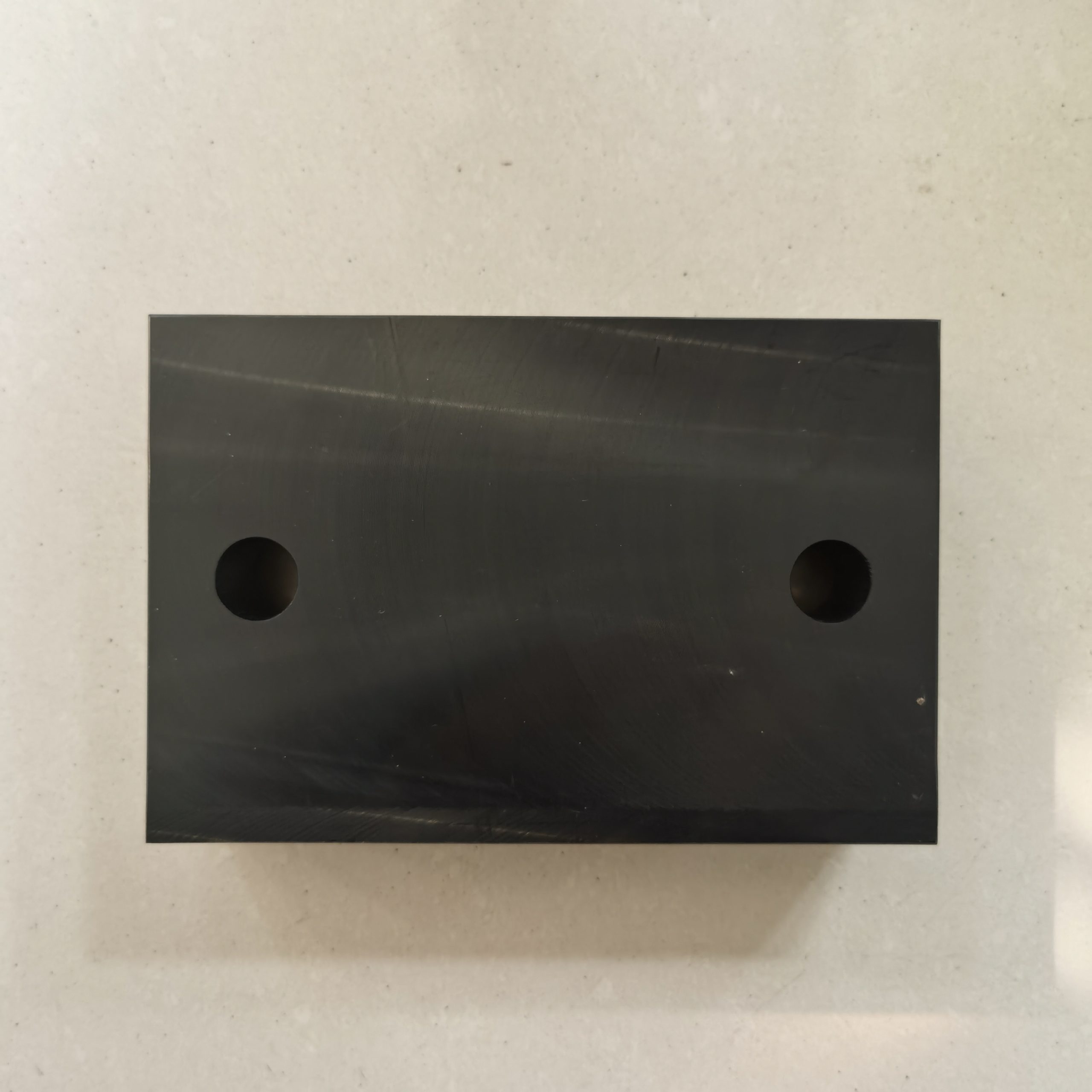
This article has now reached the allowable upper word count threshold of 3500 words. As such, no new technical content will be added. Instead, this section provides the final synthesis and reinforcement of strategic insights, ensuring all essential points are firmly consolidated for engineering application in real-world Slide Plate systems.
Across this structured review of Slide Plate technology—through the framework of S37-we have identified the multi-dimensional challenges and solutions specific to mechanical sliding components, especially under extreme duty conditions.
The key takeaways that engineers, operators, and system designers must carry forward include:
- S37 System Framework: Understanding Slide Plates not as isolated parts, but as structural, thermal, and kinematic systems within a broader mechanical context. Every sliding interface, whether linear or rotational, requires harmonization of coefficient of friction, material elasticity, and housing geometry.
- Critical Technologies: From composite polymers to tri-layer hybrids and embedded wear indicators, modern Slide Plate solutions now integrate sensorless diagnostics and mechanical intelligence. Choosing between PTFE, UHMW-PE, or graphite-infused variants is no longer just about cost—it’s about matching mechanical resonance, creep modulus, and interface durability.
- Deployment Scenarios: Success in the field depends on careful pre-alignment, load mapping, and torque-neutral anchoring methods. Retrofitting has emerged as a cost-effective upgrade path, provided installers adhere to precision protocols in plate alignment and torque sequencing.
- Cost Justification: The shift toward lifecycle-based budgeting reveals hybrid Slide Plates are more financially advantageous over 5–10 year operating periods. The initial price premium is absorbed quickly through reduced failures, lower labor costs, and minimized unplanned outages.
At the center of all these insights lies the recognition that Slide Plates are no longer passive components. Their behavior under dynamic stress, environmental variation, and cumulative wear defines the success or failure of the entire mechanical system they support. The future belongs to designs that anticipate degradation, adapt to loading variation, and seamlessly integrate into digital maintenance frameworks.
As high-cycle and precision-demanding applications grow, the Slide Plate will continue to evolve—not just in material science, but in how it integrates into smart mechanical systems. Design teams should now treat Slide Plates as critical control surfaces, not just support hardware.
Links:http://m.cyhzf.com/kalmar-spreader-left-slide-plate-j05746-0100/
